Introduction to G-Code: From Beginner Concepts to Professional Workflows
G-Code is the language that turns digital designs into physical objects. Learn what it is, how it works, where it's used and how professional workflows optimize vector files for flawless machine execution.
What Is G-Code and Why It Is Necessary
G-code (Geometric Code) is the foundational programming language for Computer Numerical Control (CNC) machinery. While design software manipulates mathematical vectors and 3D meshes, physical manufacturing machines require explicit, sequential spatial coordinates and hardware instructions.
G-code bridges this gap by translating complex digital geometries into specific linear, circular and hardware-state commands. Without G-code, microcontrollers governing stepper motors and servos cannot interpret digital design files like SVGs or STLs — rendering physical fabrication impossible.
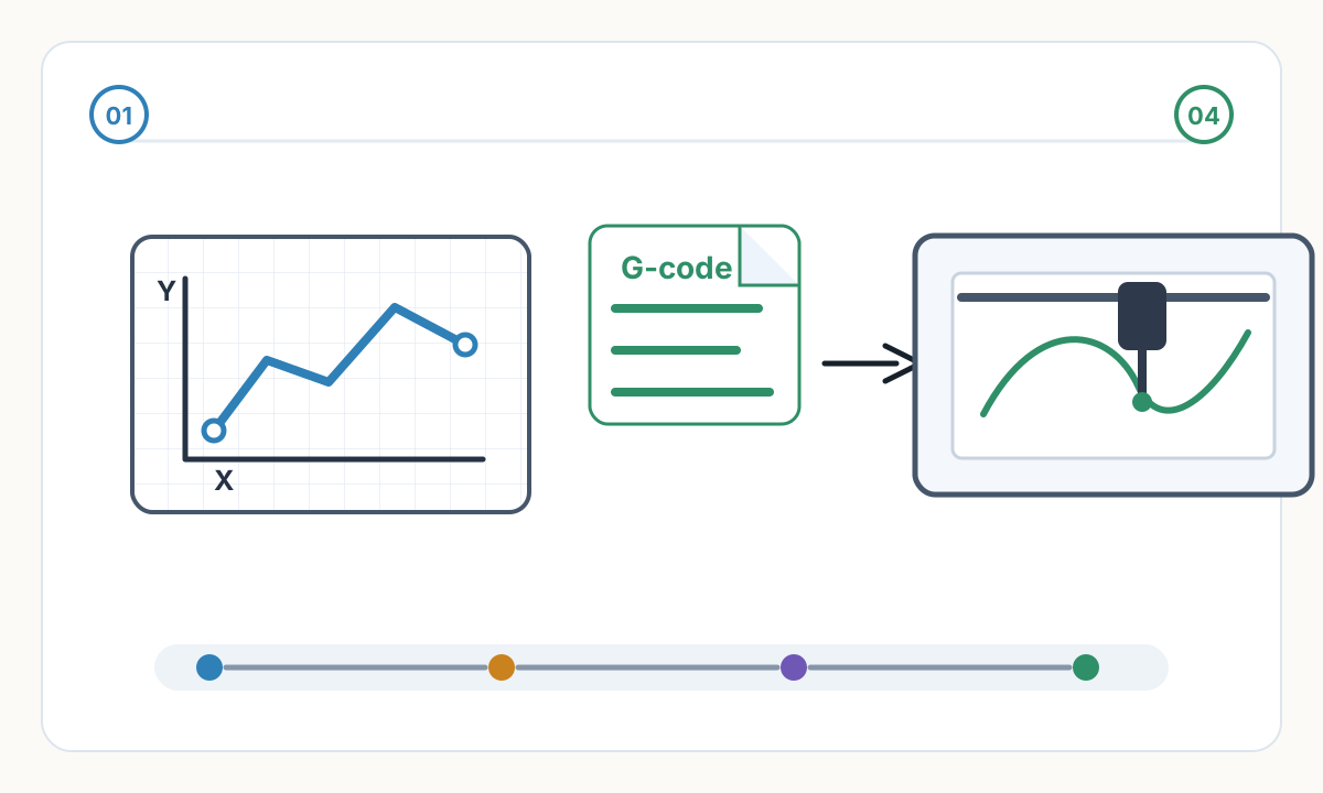

An SVG file describes what a shape looks like mathematically. G-code describes how a machine must physically move, step by step, to reproduce that shape in the real world.
Where G-Code Operates: Applications Across Industries
G-code drives virtually every machine operating on a Cartesian coordinate system, orchestrating precise physical outcomes across multiple fabrication workflows:
- Pen Plotters: G-code dictates exact X/Y positioning while utilizing Z-axis or servo commands for precise pen-up and pen-down movements to create vector art
- Laser Engravers & Cutters: G-code controls laser power modulation at specific spatial coordinates, enabling intricate raster shading or clean vector cutting
- 3D Printers: G-code maps X, Y and Z movements while synchronizing the extruder motor (E-axis) and managing thermal states for the hotend and print bed
- CNC Mills & Routers: G-code plots subtractive toolpaths through solid materials, incorporating feed rates, spindle speeds and multi-axis interpolations
The Anatomy of G-Code Commands
G-code syntax relies on alphanumeric blocks executed sequentially by the machine's firmware. A standard command, such as G1 X15.0 Y20.0 F1500 S200, breaks down into distinct operational parameters:
G-Code Command Structure
- Action Codes (G/M): G commands dictate geometry and motion (G0 for rapid transit, G1 for controlled linear movement, G2/G3 for arcs). M commands control hardware states like spindle activation or laser firing
- Coordinates (X, Y, Z): Represent absolute or relative Cartesian positions the toolhead must reach in physical space
- Feed Rate (F): Measured in mm/min, this defines the exact velocity of the toolhead during cutting or drawing operations
- Spindle/Power (S): Defines spindle RPM on CNC mills or laser intensity on laser engravers
G1 X15.0 Y20.0 F1500 S200 means: Move in a controlled line (G1) to position X=15mm, Y=20mm at a feed rate of 1500mm/min with laser/spindle power set to 200.
Common Workflows for G-Code Production
Writing raw G-code manually is highly inefficient for complex geometries. Modern workflows rely on Computer-Aided Manufacturing (CAM) software to automate toolpath generation from digital files.
The Modern Pen Plotter Workflow
- 1
Vector Design
Start with a scalable vector graphic (SVG), defined by mathematical paths rather than raster pixels. Clean, optimized SVG files produce the best G-code results.
- 2
Path Optimization
Plotter CAM software analyzes SVG paths, sorting them to minimize pen-up travel distance and prevent erratic, time-consuming machine movements.
- 3
Toolpath Generation
The software translates optimized vectors into G1 coordinates. M-codes or Z-axis shifts are inserted to physically lift and lower the pen when transitioning between unconnected segments.
- 4
Execution
A G-code sender streams the compiled file to the plotter's microcontroller (often GRBL-based), translating digital syntax into electronic pulses for the stepper motors.
Laser Engraving & 3D Printing G-Code Workflows
Laser Engraving: CAM software processes vector boundaries for cutting and raster images for shading. It generates dynamic G-code that rapidly modulates the laser's S-parameter on the fly, burning precise grayscale gradients without halting X/Y motion.
3D Slicing & Subtractive CAM: A slicer or CAM program generates 3D volumetric toolpaths, calculating material removal rates or plastic extrusion volumes while embedding exact acceleration curves and tool-change protocols into the output file.
The cleaner your input SVG, the better your G-code output. Optimized SVG files with minimal nodes, no duplicate paths and proper path ordering produce smoother, faster, more reliable machine execution.
Advanced Professional Knowledge: Post-Processors and Machine Dialects
G-code lacks universal standardization across industrial manufacturers. A Haas milling center, a Fanuc lathe and an open-source GRBL plotter interpret structural commands differently.
Professional CAM software utilizes specific Post-Processors — translation scripts that format raw toolpath data into the exact syntactical dialect required by a specific machine's controller. Customizing post-processors ensures flawless mechanical execution without manual code editing or troubleshooting.
Motion Planning and Look-Ahead Algorithms
Firmware (such as Klipper, Marlin, or GRBL) does not execute G-code instantaneously. It processes raw commands through advanced motion planners.
High-speed directional changes require precisely calculated acceleration and junction deviation algorithms to obey physics. Modern controllers parse hundreds of G-code lines ahead of the active movement (Look-Ahead).
By analyzing upcoming geometries, the firmware calculates a continuous, optimal velocity profile — preventing stuttering, skipped motor steps and mechanical resonance during complex curves.
If your G-code file contains thousands of tiny linear segments instead of smooth arcs, low-memory microcontrollers struggle to process commands fast enough. This creates stuttering, inconsistent speeds and poor surface finish.
Arc Fitting and Data Optimization
When standard vector curves (Bézier curves or splines) are exported to CAM software, they are frequently faceted into thousands of microscopic straight lines (G1 commands). This inflates file sizes massively and overwhelms low-memory microcontrollers, causing machines to stutter as data transfer bottlenecks occur.
Professional optimization workflows utilize Arc Fitting algorithms to mathematically recognize continuous curves and replace hundreds of linear segments with single G2 or G3 arc commands.
This process drastically reduces file size, ensures continuous mechanical velocity and produces perfectly smooth physical curves.
A complex curved path might generate 500 G1 line commands. With arc fitting, the same path can be represented with just 5-10 G2/G3 arc commands — a 50-100× reduction in file size and parsing overhead.
Streamline Your Workflow with Laserlinez
Transitioning from visual concepts to machine-ready G-code requires absolute precision in file conversion. At Laserlinez, we specialize in bridging the gap between digital imaging and physical fabrication.
For laser engravers and pen plotters, the Laserlinez SVG-to-G-Code service helps prepare clean SVG paths for machine-profiled output with preflight checks, a conversion report and a toolpath preview. Full CNC router CAM remains a separate workflow.
Laserlinez G-Code Workflow Benefits
- Clean, optimized SVG output with minimal node counts for efficient G-code generation
- Path optimization and ordering to reduce pen-up travel and machine time
- Production-safe geometry: no overlaps, no duplicate paths, watertight closed loops
- Direct Photo to SVG conversion for raster images — turning pixels into clean vector lines
- Scope-aware output for laser engravers and pen plotters, with CNC router CAM handled outside this service
Comments
Loading comments...