SVG to DXF Converter
...Creditsper rendering
Convert SVG to DXF for CNC, laser and CAD workflows
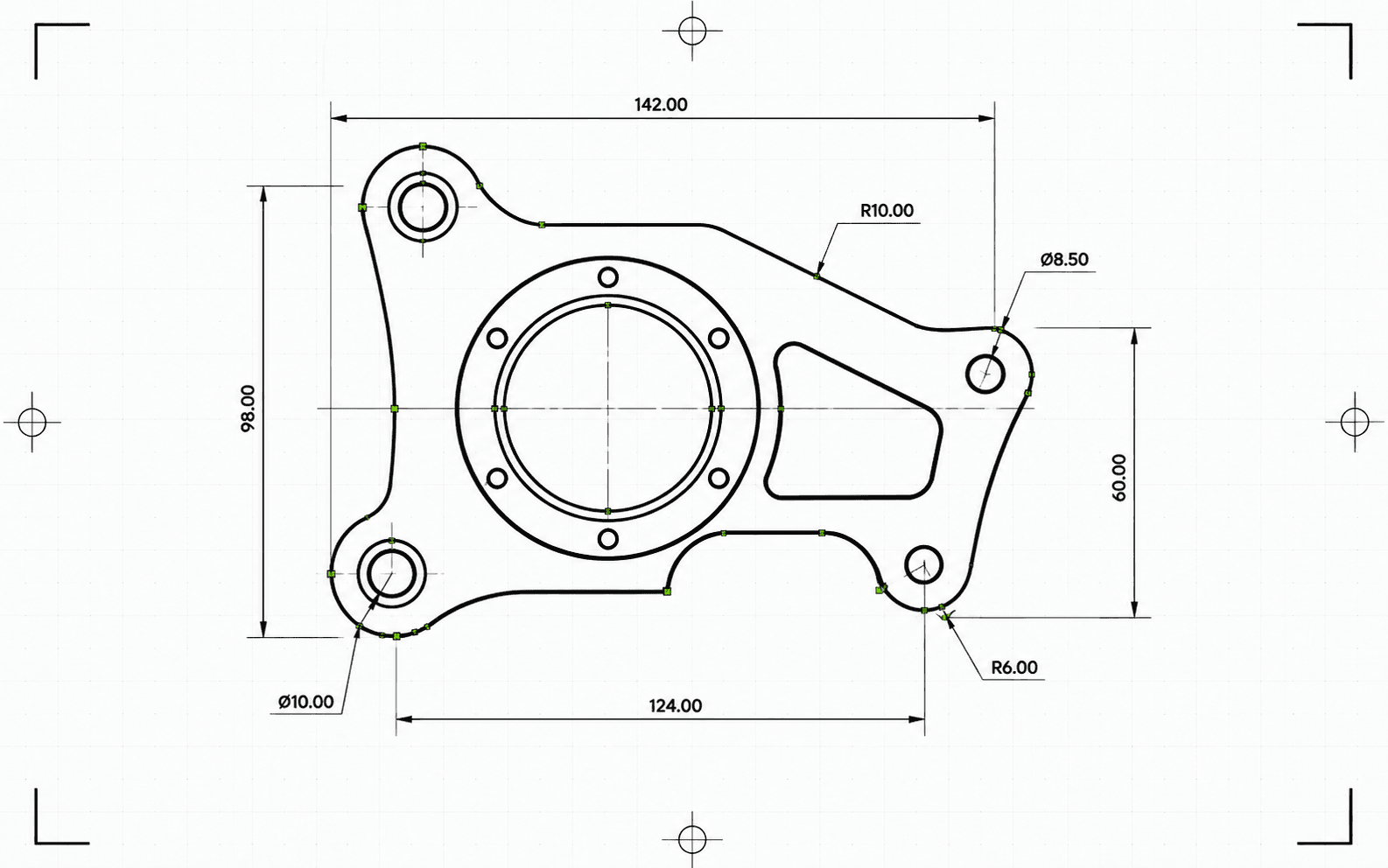
Convert path-based SVG files to DXF in millimeters, with a preflight check and a JSON conversion report. Verify the imported size and layer assignments in your receiving software.
Review the preflight report before conversion. Resolve blockers and inspect warnings, dimensions and layer assignments. A successful conversion still needs an import check and machine setup.
What the DXF conversion does to your geometry
Convert path-based SVG files to DXF in millimeters, with a preflight check and a JSON conversion report. Verify the imported size and layer assignments in your receiving software.
Vector paths in, not pictures
Convert fabrication text to outlines. Resolve clipping and masks into the intended vector paths; simply deleting them can expose unwanted geometry. Remove raster images or vectorize them first and inspect any remaining visual effects.
Confirm physical size
Set explicit SVG width and height in physical units and check the viewBox mapping. Pixel dimensions depend on a pixel-to-length convention; they do not confirm the intended part size. Measure a known feature after import.
Review curves and cleanup
Curves can be represented by arcs or straight segments. Check their deviation from the intended profile and review reported cleanup: small features and gaps may be intentional. Automatic joining or removal can change the design.
Layers and a record of what changed
Check the exported layer names and assignments, including geometry assigned to a default layer. Names and colors suggest roles; they do not configure machine operations. Prefer an existing preset DXF when the receiver already accepts it.
Laserlinez delivers geometry, not a machine job. Which layer is cut, scored or engraved — and the power, speed, passes, tool and depth, kerf compensation, lead-ins and cut order — is set in your laser or CAM software.
Output artifacts
DXF - CAD file
DXF output in millimeters for CAD import, laser software, CAM handoff and vector archiving.
JSON - Conversion report
Structured preflight and delivery report with status, blockers, warnings, dimensions, layers, entity counts, cleanup actions and checksums.
How it works
- 1
Upload a clean SVG
Convert fabrication text to outlines. Resolve clipping and masks into the intended vector paths; simply deleting them can expose unwanted geometry. Remove raster images or vectorize them first and inspect any remaining visual effects.
- 2
Automatic file validation
Review the preflight report before conversion. Resolve blockers and inspect warnings, dimensions and layer assignments. A successful conversion still needs an import check and machine setup.
- 3
Download DXF and report
A successful conversion provides a DXF file and a JSON report. Confirm the exported DXF version with the receiver, inspect the geometry and configure operations and machine settings in your laser or CAM software.

Get credits now and start rendering
Best use cases
CAD handoff
Prepare SVG logos, layouts, labels, drawings and diagrams for CAD applications that need DXF input.
Laser cutting prep
Check the exported layer names and assignments, including geometry assigned to a default layer. Names and colors suggest roles; they do not configure machine operations. Prefer an existing preset DXF when the receiver already accepts it.
CNC layout exchange
Create a DXF exchange file for downstream CAD/CAM setup. Toolpaths, Z-depth, tabs, pocketing and cutter compensation remain in CAM software.
Technical archive
Store client artwork and production drawings in a CAD-friendly vector format with report-backed provenance.
Layered production files
Check the exported layer names and assignments, including geometry assigned to a default layer. Names and colors suggest roles; they do not configure machine operations. Prefer an existing preset DXF when the receiver already accepts it.
SVG preflight
Run a dry-run conversion to detect unsupported features, ambiguous dimensions and geometry problems before starting a full conversion.