Technical Drawing with Pen Plotters
Pen plotters excel at technical and architectural drawings requiring precision and consistent line quality. Understanding drafting standards and CAD integration produces professional engineering documentation.
Line Weight Standards
Line weight hierarchy conveys information: thick lines for outlines and major elements, medium for secondary features, thin for dimensions and hatching, very thin for construction geometry. ISO standard line widths: 0.13, 0.18, 0.25, 0.35, 0.50, 0.70, 1.00, 1.40, 2.00mm. Select pen sizes matching these standards for professional appearance.
Architectural conventions: walls in section (cut through) receive heaviest lines (0.70-1.00mm), wall elevations medium-heavy (0.50mm), doors/windows medium (0.35mm), furniture and fixtures light (0.25mm), dimension lines very light (0.18mm). Hierarchy guides eye—immediately clear what's structural vs decorative.
Mechanical drafting: part outlines heavy (0.50-0.70mm), hidden lines dashed medium (0.35mm), center lines thin dash-dot (0.25mm), dimension lines thin (0.18mm), section hatching very thin (0.13mm). Precision critical—line weight consistency communicates engineering intent accurately.
Pen selection for technical work: technical pens (Micron, Staedtler) provide exact widths, multiple pens needed for complete weight range. Set of 4-6 pens covers most needs (0.18, 0.25, 0.35, 0.50, 0.70mm). Ballpoint acceptable for less critical work but lacks width precision. Never use variable-width pens (fountain) for technical drawings—defeats purpose of standardized weights.
CAD line weight mapping: CAD software assigns colors to line weights (color-by-layer convention). Example: red = 0.70mm, blue = 0.35mm, green = 0.25mm. Plotter software recognizes colors and selects appropriate pen automatically. Requires: loading correct pens in order, configuring color-to-pen mapping, verifying mapping before plot.

Dimensioning and Annotation
Dimension lines: thin lines (0.18mm) with arrows or tick marks at ends, numerical value centered above or within line, extension lines project beyond dimension line slightly. Spacing: dimension lines minimum 8mm from object, 6mm between parallel dimension lines. Consistency matters—sloppy spacing appears unprofessional.
Arrow styles: closed filled arrows (architectural standard), open arrows (mechanical), tick marks (European), dots (rare). Choose one style, use throughout drawing. Arrow size proportional to line weight—typical 3-4mm long for 0.18mm dimension line. Too large dominates drawing, too small invisible.
Text height: minimum 2.5mm for legibility (roughly 10pt font), 3.5-5mm common for titles, 2.5-3mm for dimensions, 2mm for notes. Smaller text illegible in reduced prints or from viewing distance. Technical drawings often reduced 50% for distribution—design text sizes accordingly.
Font selection: use technical lettering fonts (DIN, Helvetica, Arial) not decorative fonts. Avoid serifs—thin strokes disappear at small sizes. Handwriting fonts acceptable for artistic architectural renderings but not engineering drawings. Consistency: one font throughout drawing, vary size for hierarchy only.
Leader lines: thin lines (0.18mm) connecting notes to features, terminate with arrow at feature, horizontal note text at other end. Angle leaders 30-60° for clarity—vertical or horizontal leaders confuse with dimension lines. Avoid crossing leaders—route around or rearrange notes.
CAD to Plotter Workflow
- 1
Prepare CAD Drawing
Organize layers logically: walls, dimensions, text, furniture each on separate layer. Assign colors by line weight: layer properties set color corresponding to desired pen. Verify no duplicate geometry (select all, check count). Set correct units and scale. Create layout/paper space view at final plot size. Add title block, scale bar, north arrow, drawing notes.
- 2
Export to Plotter Format
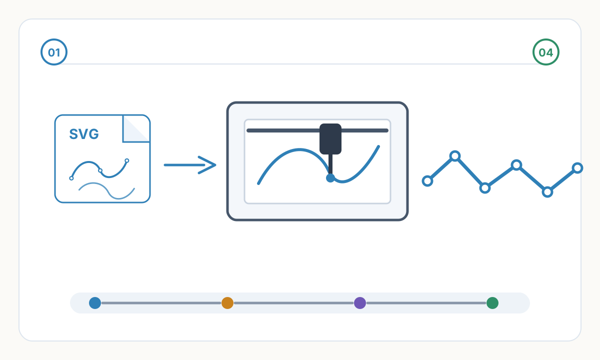
Export options: PDF (universal but rasterizes text), DXF (preserves vectors), SVG (plotter-native). Recommended: export to PDF, then convert to SVG via Inkscape for plotter compatibility. Verify export: check line weights preserved, text converted to outlines or remains editable, dimensions accurate, scale correct. Test print small section before full plot.
- 3
Configure Plotter Software
Map colors to pens: color 1 = pen in holder 1 (0.70mm), color 2 = pen 2 (0.35mm), etc. Set plot speed: slower for precision (150-250mm/s), faster for large fills (400mm/s). Define paper size and orientation. Enable optimization (path sorting) to reduce plot time. Save configuration as preset for future technical drawings.
- 4
Plot and Verify
Load technical drawing paper (vellum or bond), install pens in correct holders (verify widths match mapping), plot test section (corner with title block and detail), verify: line weights correct, dimensions legible, text clear, scale accurate. If satisfactory: plot full drawing. If issues: adjust pen pressure, check pen ink flow, re-export from CAD if geometry wrong.
Technical Drawing Applications
Architectural floor plans: walls shown in plan view (from above), thickness represents actual wall thickness at scale (e.g., 200mm wall at 1:100 scale = 2mm line). Doors swing direction shown, windows drawn as openings, room labels centered in spaces, dimension strings along edges. Scale typically 1:100 or 1:50 for residential, 1:200 for large buildings.
Mechanical parts: isometric or orthographic projection (top, front, side views), section cuts showing internal features, detail callouts for complex areas, dimensions defining all critical measurements, tolerances specified for precision parts. Scale varies: 1:1 for small parts, 1:2 or 1:5 for larger assemblies.
Electrical schematics: single-line diagrams showing power distribution, detailed schematics with component symbols, wire routing diagrams, panel schedules and legends. Line weight less critical than clarity—all lines often same weight. Symbols follow standards (ANSI, IEC). Labels crucial—every wire numbered or coded.
Site plans: buildings shown in context of property, topography with contour lines, trees and landscaping symbols, property boundaries and setbacks, utilities (water, sewer, electric) routing, north arrow and scale bar. Large scale (1:500, 1:1000) fits entire property. Requires large format plotter for legibility.
Detail drawings: enlarged views of specific features, callout bubbles referencing detail on plan, scale noted clearly (often 1:5 or 1:10), annotation dense—every dimension needed for construction, section cuts showing assembly sequence or layering. Details supplement overall drawings providing buildable information.
Professional Standards and Best Practices
Title blocks: located lower right corner (last item visible when folded), contains: project name, drawing title, scale, date, drawn by, checked by, revision history, company logo, drawing number. Standardize title block across project—professional consistency. Template once, reuse forever.
Border and margins: drawing border inside paper edge (typically 10-15mm margin), border thin line (0.25mm), trim marks at corners if drawing will be cut to size. Margins prevent important information lost if edge damaged or trimmed during copying/binding.
Revision tracking: revision clouds (cloud-shaped boundary highlighting changes), revision table listing date, description and who approved, revision letters or numbers in title block. Critical for construction documents—contractor must know which version current, what changed between revisions.
Sheet organization: cover sheet with index of all drawings, general notes and legends, plans before sections before elevations before details (general to specific), consistent sheet numbering (A1.0, A1.1... for architectural, S1.0... for structural, etc.). Navigation easy—anyone can find specific drawing quickly.
Printing and distribution: plot to archival paper for records (100+ year lifespan), use PDF for digital distribution (universally viewable, maintains scale for printing), provide both full-size and half-size sets (half-size for review, full-size for construction), number sets and track distribution. Professional project management prevents confusion about which drawings current.
Verification checklist before production
- Confirm final size, units and orientation in the destination software
- Inspect the file for hidden, duplicate, or irrelevant geometry
- Run a small material or test engraving before full production
- Save the approved settings, source file and exported production file together
Comments
Loading comments...